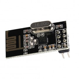
The Nordic NRF24L01+ 2.4Ghz radio board is a great little radio to use for all your projects. No, it is not wifi compatable. It uses it’s own protocal but it is very easy it integrate into an Arduino project, is low power, and is very small. Don’t let the size fool you though, it can transmit over some impressive distances.
This article wil lgo over the basic wireing connections and an inital sketch to make sure it is working.
The first thing that you should do is buy at least two of them. They are cheap and you will need two of them to create a simple link between Arduino projects. Be careful when purchasing the boards. There are a lot of cheap clones out of China. Name sure to pick up the NRF24L01+ and not the NRF24L01 (the plus sign is important).
Project Parts list:
- 2 x NRF24L01+ Radio Boards
- 2 x Arduino boards (I use the 3v Trinket Pro from Adafruit)
- 1 x 36 pin female header
- 1 x 36 pin break-away male header
- 1 x double sided perf board
- 2 x breadboards (or one large one)
Preparation:
The NRF24L01+ board does not have a very friendly connector. The connector on it is a 2×4 (8 pins total) connection. The first thing we will do is msake some adaptor board so that it is easier to plug them into our breadboards. Once you have made these adaptors, then you can use them for lots of things.
Take the 36 pin female header and cut off 4 sections. Each section should have 4 pins. If you take the header and pull out every 5th pin then that makes a eacy place to break the header. Next take the 36 pin male header and break it into 4 sections. Each with 4 pins. Cut the double sided perf board into two small perf boards. The perf board should each be at least 4 holes wide by 4 holes deep.
Take one of the perf boards and lets built one of the adaptors. In the two middle rows solder the female headers on. Placing them beside each other so they form a 2 x 4 header socket that the NRF24L01+ will fit into. Next on the opposite side, solder the male headers so that they are on either side of female headers but stick out the opposide way (see images). Then carefully solder each make pin over to the female pin right beside it. This will then allow the adaptor to be plugged into the breadboard.
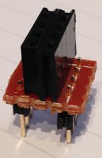
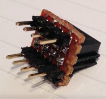
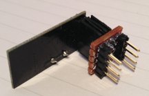
Once you have one adaptor built, start over and build the other one.
Making the connections:
Plug the Trinket and the NRF24L01+ radio adaptor board we built into the breadboard. If you make all the connections on your adaptor board correctly them the pin numbers on the adaptor board should be laid out the same way as the pins on thr NRF24L01+ board (just a little wider out). I find it easier to make the wire connections and then plug in the NRF24L01+ board. Connect the board to the Trinket as follows:
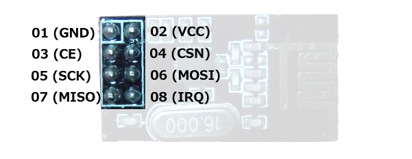
| Line Name | NRF24L01+ Pin | Arduino Pin |
| Gnd | 1 | GND |
| 3v3 | 2 | 3v3 |
| CE | 3 | 9 |
| CSN | 4 | 10 |
| SCK | 5 | 13 |
| MOSI | 6 | 11 |
| MISO | 7 | 12 |
Once you get thinks wired up on the breadboard, it should look someting similar to this:
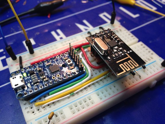
Done forget that we need to build two of these bords in order to test (we need something to talk to).
The Software:
Download the RF24 library from github. You can sine the repository here with all the documentation. If you just want to download the latest library code then click here although you should check out the documentation. Once you download the library, unzip the code into you ‘libraries’ folder in the Arduino IDE and then restart the Adriuno IDE. If you are not sure how to install the library code or this is your first time, check out the documentation here.
From the file menu in the Arduino IDE, select ‘Examples’ then ‘RF24’ and finally the “GettingStarted” example. This will load the GettingStarted example. Take a look over the code in the getting started example. There is very liitle you will have to edit. For our test make sure that you change the radioNumber = 0 to radioNumber = 1 when you fladh the code into the second board. For our example, you should not have to change the RF radio(7,8) line. If you had to wire up your RF24L01+ a little different, then you may need to change this line as well.
/****************** User Config ***************************/
/***      Set this radio as radio number 0 or 1         ***/
bool radioNumber = 0;
/* Hardware configuration: Set up nRF24L01 radio on SPI bus plus pins 7 & 8 */
RF24 radio(7,8);
Upload the sketch into both of the boards. Start the serial montor on one with the baud rate set to 115200 and you should see something similar to the following:
 RF24/examples/GettingStarted/
ROLE: Pong back
STATUS = 0x0e RX_DR=0 TX_DS=0 MAX_RT=0 RX_P_NO=7 TX_FULL=0
RX_ADDR_P0-1 = 0xf0f0f0f0d2 0xf0f0f0f0e1
RX_ADDR_P2-5 = 0xc3 0xc4 0xc5 0xc6
TX_ADDR = 0xf0f0f0f0d2
RX_PW_P0-6 = 0x08 0x08 0x00 0x00 0x00 0x00
EN_AA = 0x3f
EN_RXADDR = 0x03
RF_CH = 0x4c
RF_SETUP = 0x07
CONFIG = 0x0f
DYNPD/FEATURE = 0x00 0x00
Data Rate = 1MBPS
Model = nRF24L01
CRC Length = 16 bits
PA Power = PA_HIGH
Both boards well automatically come op in listen mode. To start the test, press “T” in the monitor on one of them. This will put that unit into transmit mode and it will send out a “ping” test to the other unit. If all goes well and your other unit is running, you should see something similar to this:
Now sending 90...ok...Got response 90, round-trip delay: 28
Now sending 1122...ok...Got response 1122, round-trip delay: 26
Now sending 2152...ok...Got response 2152, round-trip delay: 27
Now sending 3182...ok...Got response 3182, round-trip delay: 29
Now sending 4214...ok...Got response 4214, round-trip delay: 27
Now sending 5244...ok...Got response 5244, round-trip delay: 29
Now sending 6277...ok...Got response 6277, round-trip delay: 26
If you see the above, congratulaions. Your NRF24L01+ boards are working fine and you have just created your first wireless link with them.
What now?…
Now that you have setup your first wireless link, this opens up a lot of new and cool projects you can do with them. Have fun and experiment. Yuo may alreadt have a few ideas in mind but if not, here are a few of my favorites.

